Spice Values
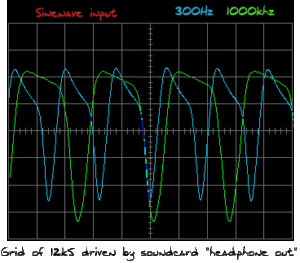
Below are the simulated transients, plate voltage and speaker current, with a 1k signal put through the model. If you take a look at the tube curves below, you can see that the 12u7 values are a bit closer than the 12k5 values. Interesting enough the “S” like curve showed up after I changed the SC-grid to be fed off the same supply as the plate (no bypass cap or resistor)
-I used trial and error, after the capture failed to give good results and quit trying after a while (both times!) …Close is good enough for hobby work.
Frequency Response (roll-over)
R2 mod from 68K to 470k as was suggest by Stephane, this rollover shows the DPDT switch I put in to change input and cathode values. Switches from bright/clean (schematic above) to bloated growl. Since I will usually play this amp with an eq in front, it should give me a lot of tonal flexibility.
Frequency Response Overlay

(12-11-04) Stephane produces a schematic frequency modeled after a tweed champ. Here is a overlay of my amp with his champ version,Seems to have similar curves to my bloated version only greater output. When I get a chance I’ll need to try his new circuit. The spice frequency reading was taken on the positive terminal of the speaker model.
12U7 Model
*attempt at a 12u7 using koren calq
*
.SUBCKT 12u7kor 1 2 3 ; P G C;
+ PARAMS: MU=21.95 EX=1.1 KG1=1082.66 KP=68.5 KVB=490.4 RGI=1000
+ CCG=2.3P CGP=2.2P CCP=.9P ; ADD .7PF TO ADJACENT PINS; .5 TO OTHERS.
E1 7 0 VALUE=
+{V(1,3)/KP*LOG(1+EXP(KP*(1/MU+V(2,3)/SQRT(KVB+V(1,3)*V(1,3)))))}
RE1 7 0 1G
G1 1 3 VALUE={(PWR(V(7),EX)+PWRS(V(7),EX))/KG1}
RCP 1 3 1G ; TO AVOID FLOATING NODES IN MU-FOLLOWER
C1 2 3 {CCG} ; CATHODE-GRID; WAS 1.6P
C2 2 1 {CGP} ; GRID-PLATE; WAS 1.5P
C3 1 3 {CCP} ; CATHODE-PLATE; WAS 0.5P
D3 5 3 DX ; FOR GRID CURRENT
R1 2 5 {RGI} ; FOR GRID CURRENT
.MODEL DX D(IS=1N RS=1 CJO=10PF TT=1N)
.ENDS
*
*
12K5 Model
* attempt at a 12k5 tube model
*Getting closer!
*curves developed the s character when SC-grid and plate were fed off the same supply
.SUBCKT 12k5korb 1 2 3 4 ; P G1 C G2
+ PARAMS: MU=13.7 EX=.39 KG1=74 KG2=500 KP=31 KVB=.99
+ CCG=4.6P CPG1=1.01P CCP=8P RGI=1k
RE1 7 0 1G ; DUMMY SO NODE 7 HAS 2 CONNECTIONS
E1 7 0 VALUE= ; E1 BREAKS UP LONG EQUATION FOR G1.
+{V(4,3)/KP*LOG(1+EXP((1/MU+V(2,3)/V(4,3))*KP))}
G1 1 3 VALUE={(PWR(V(7),EX)+PWRS(V(7),EX))/KG1*ATAN(V(1,3)/KVB)}
G2 4 3 VALUE={(EXP(EX*(LOG((V(4,3)/MU)+V(2,3)))))/KG2}
RCP 1 3 1G ; FOR CONVERGENCE
C1 2 3 {CCG} ; CATHODE-GRID 1
C2 1 2 {CPG1} ; GRID 1-PLATE
C3 1 3 {CCP} ; CATHODE-PLATE
R1 2 5 {RGI} ; FOR GRID CURRENT
D3 5 3 DX ; FOR GRID CURRENT
.MODEL DX D(IS=1N RS=1 CJO=10PF TT=1N)
.ENDS
————————————–
|
Amp simulation
|